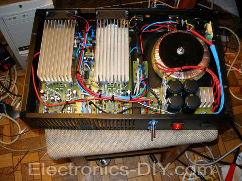
400W Stereo Audio Amplifier based on the original Marshall Leach involvement, but has made some improvements. Regarding the power supply voltage to the +-75V. VC comparing the performance of the modified Leach 700W/2R on one common board of both channels, as well as protection and control circuits for the fans. Compared to the 700W version a bit different in wiring. Because some things in the 700W version is completely tightened to perfection.

700W version could criticize a couple of things:
1st very high gain output stage resulting in deterioration of signal noise distance. Therefore 700W version even more noisy.
2nd The absence of multipliers Ube bias current control and maintain temperature stability diagram. The 700W version of the thermal stabilization solved by a single transistor, which can sometimes cause a great loss due to power control is fast enough and has some delays. Therefore JPA400 added to this multiplier.
3rd Protection Error on board speakers, the amplifier is less comfortable and it is necessary to add this protection to the side somewhere special plate.
4th no possibility to correct the offset voltage of the amplifier output, this has a rather large weight in the differential pair of transistors and voltage level. Here this is solved by means of trimmer connected to the input Mark
5th The work points the individual stages are laid pretty low, it will also cause an increase in total harmonic distortion as well as intermodulačního distortion.
All this is in JAP400 removed. The input amplifier is Mark with adjustable offset voltage. Mark is mainly due Preamplified signal for generating the actual end-impedance amplifiers and separates. The differential amplifier is a classic symmetrical with the current 5 mA per couple, which is about 2.5 mA each transistor. Equally, shifted the operating point voltage amplifier to approximately 13 mA. This modified driver will provide enough power for generating terminal transistor and is hard enough. At the end of this time is five pairs of end-type transistor 2SC5200 / 2SA1943. Current policy is converted into the number of transistors. It has a negative slope and replicates the characteristics of SOAR terminal transistors. Current protection for amplitude limitation limits the end-around transistors 7A. As has been mentioned on the thermal stabilization of the multiplier is used Ube, is formed by two NPN and PNP transistors.
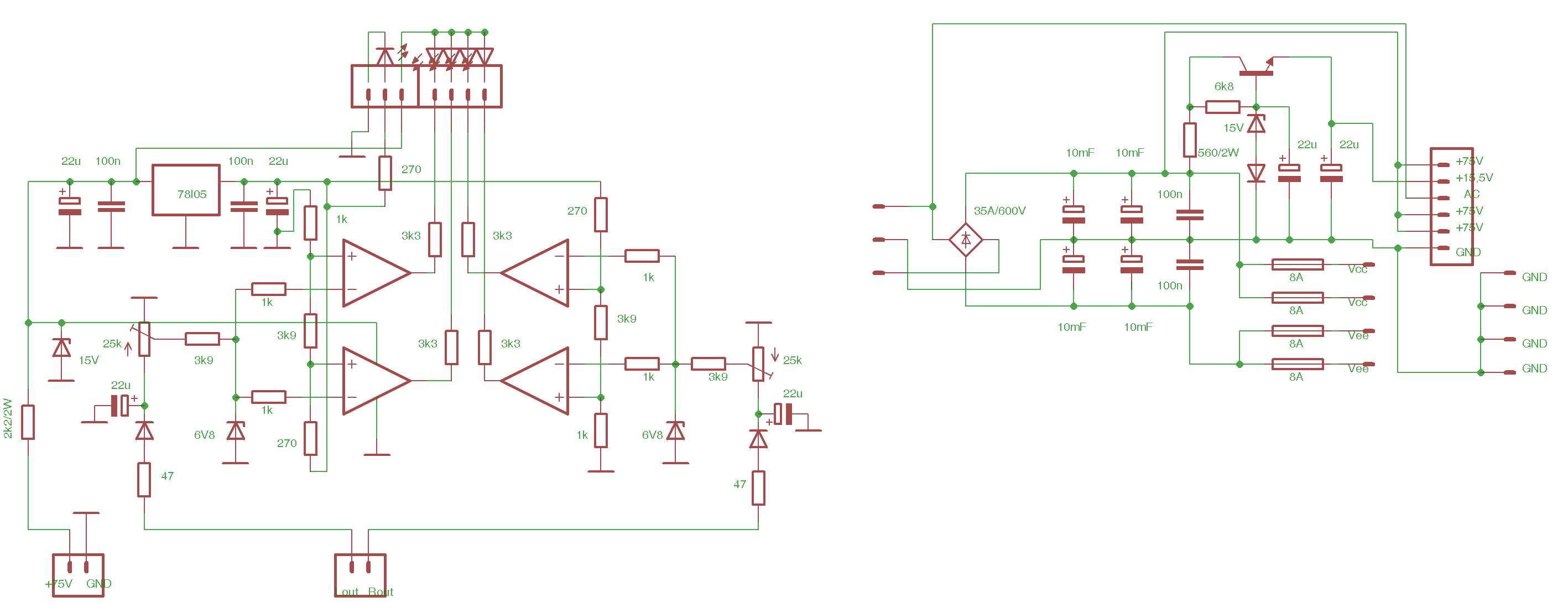
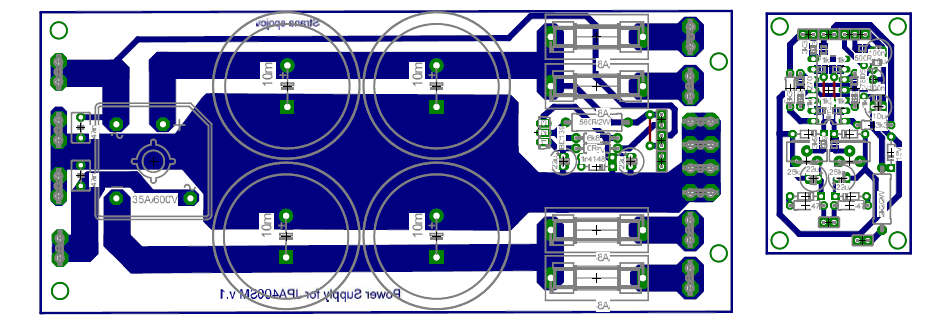
The board also includes an amplifier circuit for the fan control. This circuit ensures that the fan speed control depending on temperature. At the temperature to 65 ° C, fan runs for about 30%, it greatly reduces noise. After exceeding this temperature, the fans start running at 100% and lights to signal overtemperature. fans again at reduced power switch at about 42 ° C. Thermal protection is associated with protection of the speakers at cooler temperatures exceeding 80 ° C, the speaker is disconnected. On board is a relay switch that allows stereo / bridge mode, the indikovám LED on the front panel. The amplifier also includes an auxiliary power source to the main board, formed by transistor stabilizer. Due to higher electric circuit protection circuit and fan control. There is also an indicator of an excited, solved by the presence of the indicator signal and clip detector.
Technical parameters:
Output power: 2x 400W/4R, 2x230W/8R
Minimum impedance: 4R
Slew rate: 45V/us
Bandwidth: 8-150 000 Hz /-3dB
Maximum permissible voltage: +-75V
Filter Capacity: 2 x 20G / 80V
Sensitivity DC protection: + /-2V
Late connection: 2 seconds
Fusing end amplifier: 4 8 A / F
Input sensitivity for maximum excitation: 1V


